Visible surfaces
Texture, color and appearance zones define where molding marks and surface variation need particular attention.


Automotive Components
JTO supports tooling and injection molding for automotive plastic components, connecting part geometry, surface requirements and assembly interfaces from engineering review through production.
INDUSTRY CONTEXT
Automotive plastic components bring visible surfaces, internal supports and mating interfaces into one part system. Tooling and molding decisions need to consider how the part looks, locates and joins surrounding components.
Texture, color and appearance zones define where molding marks and surface variation need particular attention.
Locating features and reference surfaces establish the relationship between adjoining parts, including specified gaps and flushness.
Clips, bosses and fastening points connect molded geometry to assembly access and retention requirements.
Material selection and verification requirements follow the component’s location, expected exposure and customer specification.
PRODUCT / COMPONENT CONTEXT
A molded automotive component combines a finished outer surface with ribs, mounting points and locating features. Review these features together so appearance and assembly requirements inform the tooling approach.
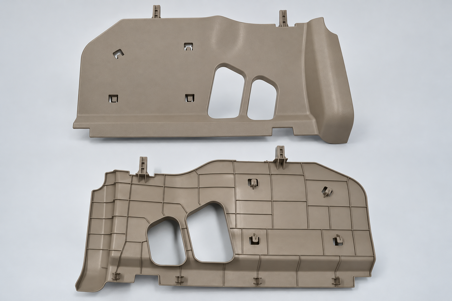
Concept illustration of automotive plastic part features; not a customer project or validated assembly design.
Define texture, color and appearance zones, including areas where sink marks, weld lines or gate marks require attention.
Review wall transitions, rib layout and fastening features together with molding and assembly requirements.
Establish attachment positions, locating references and access for assembly.
Define adjoining-part geometry, target gaps and flushness requirements against agreed datums.
MANUFACTURING REQUIREMENTS
Connect the part drawing, material specification and assembly references to a clear basis for tooling, sampling and inspection.
Review draft, parting direction, undercuts, openings and tool access against the component geometry.
Evaluate wall transitions, ribs and bosses alongside the specified resin and expected molding behavior.
Identify reference surfaces, locating points and critical dimensions that govern adjoining-part position.
Define visible zones, texture references and acceptance criteria for molding marks and surface variation.
Keep fastening features, mating references and approved drawing revisions aligned throughout sample review.
Automotive Components project information
RELEVANT JTO CAPABILITIES
Select the manufacturing scope around the component’s geometry, material, finish and assembly needs.
Translate part geometry, surface requirements and attachment features into tooling decisions.
View capabilityCoordinate material and process conditions around dimensional stability, appearance and fit.
View capabilityReview finishing, inserts, fastening and component assembly requirements where specified.
View capabilityKeep drawings, open issues, sample feedback and approval decisions aligned with the current revision.
View capabilityCONNECTED MANUFACTURING
A consistent drawing and acceptance basis connects engineering decisions to tooling, molded samples and assembly checks.
Establish geometry, material, visible surfaces and mating references before tooling decisions are finalized.
Review parting, release and feature-forming requirements against the agreed component definition.
Compare dimensions, appearance and assembled fit with the current drawing and agreed references.
QUALITY & RISK CONTROL
Agree the inspection basis around the features that matter to the component’s appearance and assembly. Customer-specific validation requirements should be identified during project review.
Check critical dimensions, reference surfaces and mounting positions against the approved drawing.
Compare texture, color and visible molding marks with agreed samples or appearance criteria.
Review clip, boss and fastener positions together with assembly access and specified retention requirements.
Assess adjoining-part alignment, gaps and flushness using the agreed mating references.
PROJECT PATH
Start with available part data. Agree the tooling scope, trial samples, checks and approval responsibilities before production.
Part data, product context and open requirements.
Geometry, interfaces, material direction and manufacturing questions.
Tool-related decisions where required by the component path.
Sample condition and comparison basis for the next review.
Relevant dimensional, surface and assembly checks.
Visible findings, actions and readiness decision.
NEXT STEP
Share your drawings, material requirements, appearance references, mating-part information, quantities and target dates. Use the Project Guide to prepare the inputs for review.