PART GEOMETRY
3D data and geometry relevant to mold construction.

Precision Tooling
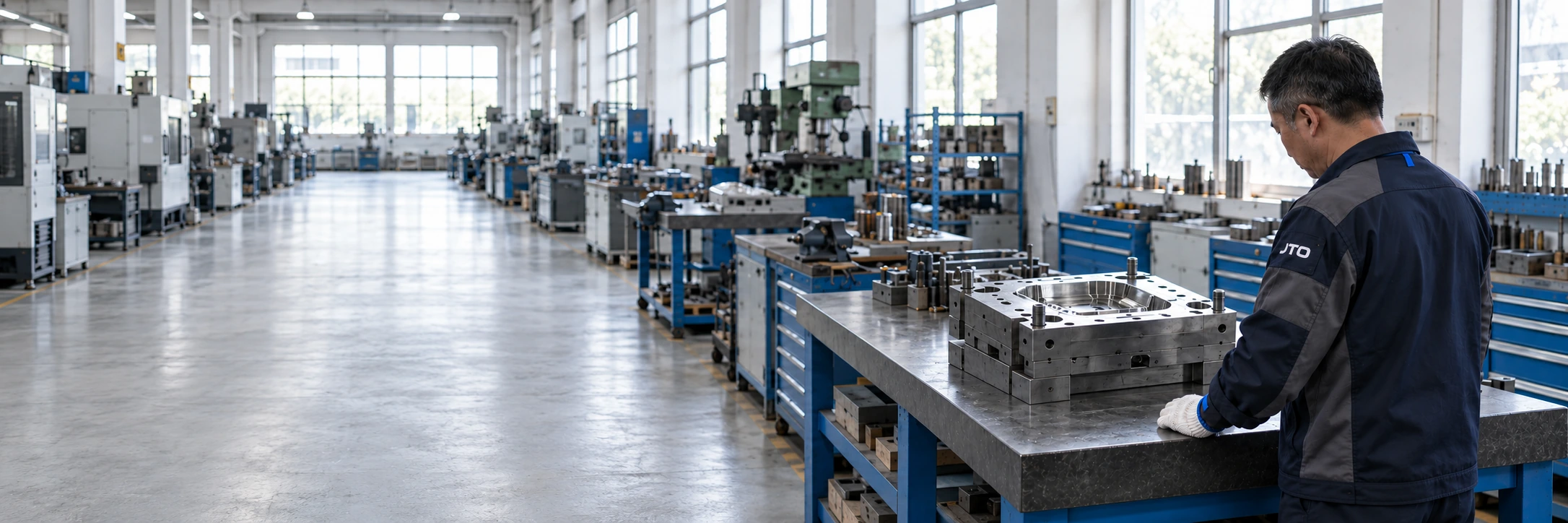
JTO designs and builds injection molds, from part feasibility and mold design through machining, fitting and trials.
CAPABILITY ROLE
Tooling is the physical bridge between part definition and repeatable molding.
Geometry, material direction, critical interfaces and production expectations influence how the mold is designed, built and reviewed.
ENGINEERING INPUTS
Share current drawings, resin requirements, expected quantities and the intended molding setup.
3D data and geometry relevant to mold construction.
Defined dimensions, tolerances and important interfaces.
Known material family or application requirement.
Texture, appearance, finish or visible-part expectations.
Assembly points, sealing areas, clips, bosses or other critical relationships.
Expected production context, volume direction and downstream requirements.
Precision Tooling project data
CORE WORK
Agree the operations and acceptance criteria required for your part.
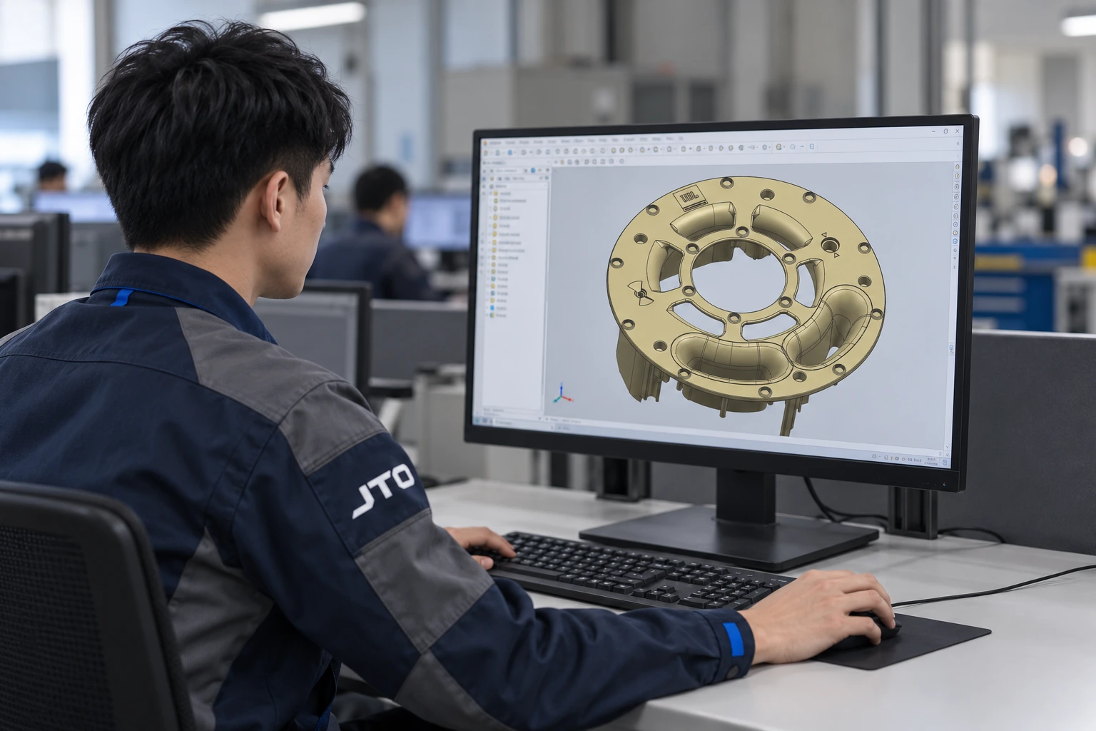
Part definition and physical reference provide a shared work context for DFM, mold design and machining decisions.
Review part geometry, interfaces and manufacturing concerns before tooling decisions are locked.
Translate part definition into mold structure, interfaces and manufacturing references.
Produce mold components according to the approved tooling definition.
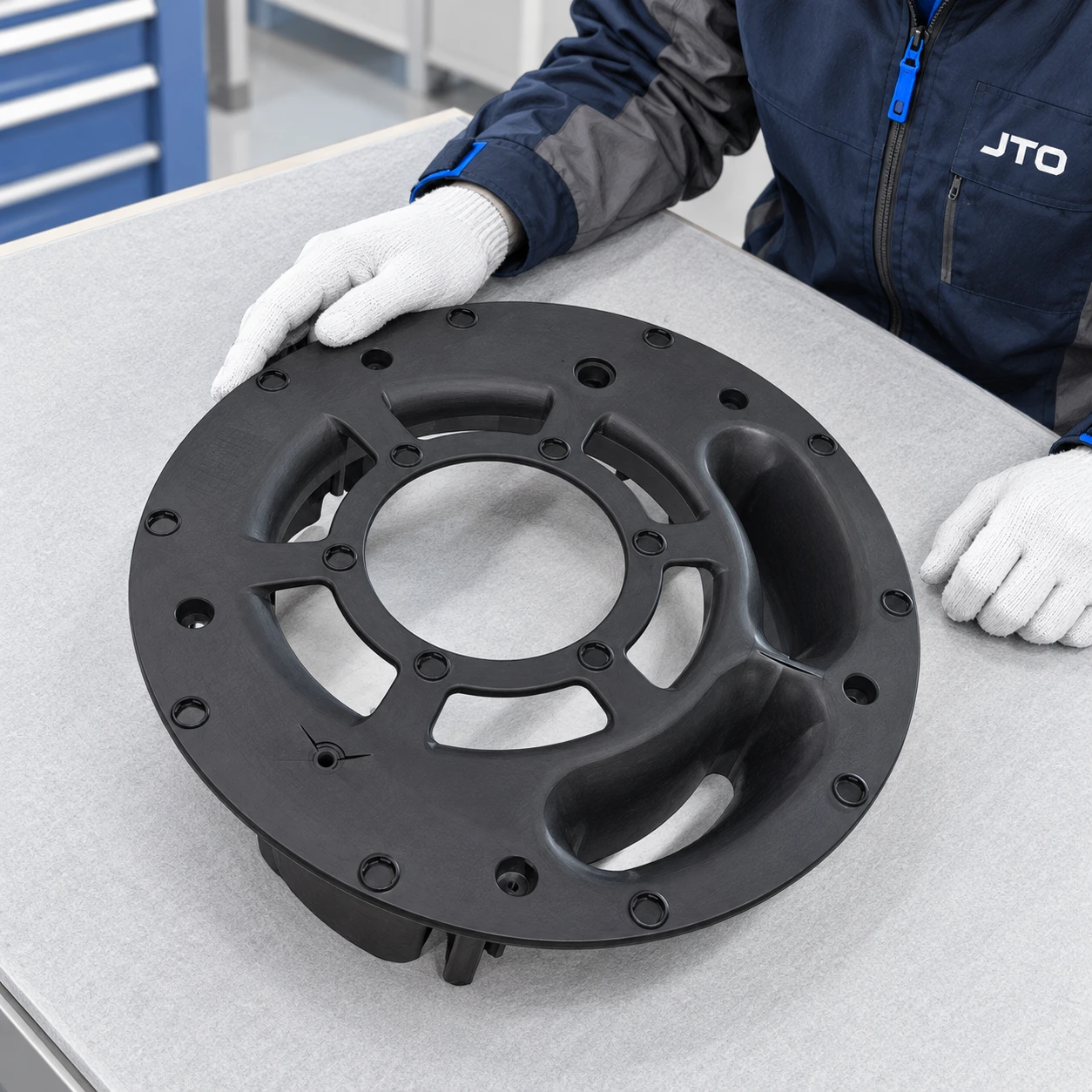
Illustrative component and digital reference; no tool-to-part project relationship is established.
Bring tooling components together and review physical fit and mold condition.
Use molding trials and sample parts to evaluate the tool in manufacturing context.
Adjust tooling where trial findings, part condition or approved revisions require change.
PROCESS ILLUSTRATIONS
Illustrative tooling and manufacturing scenes.
Tool structure, drawing context and review activity connect the physical mold with its engineering definition.
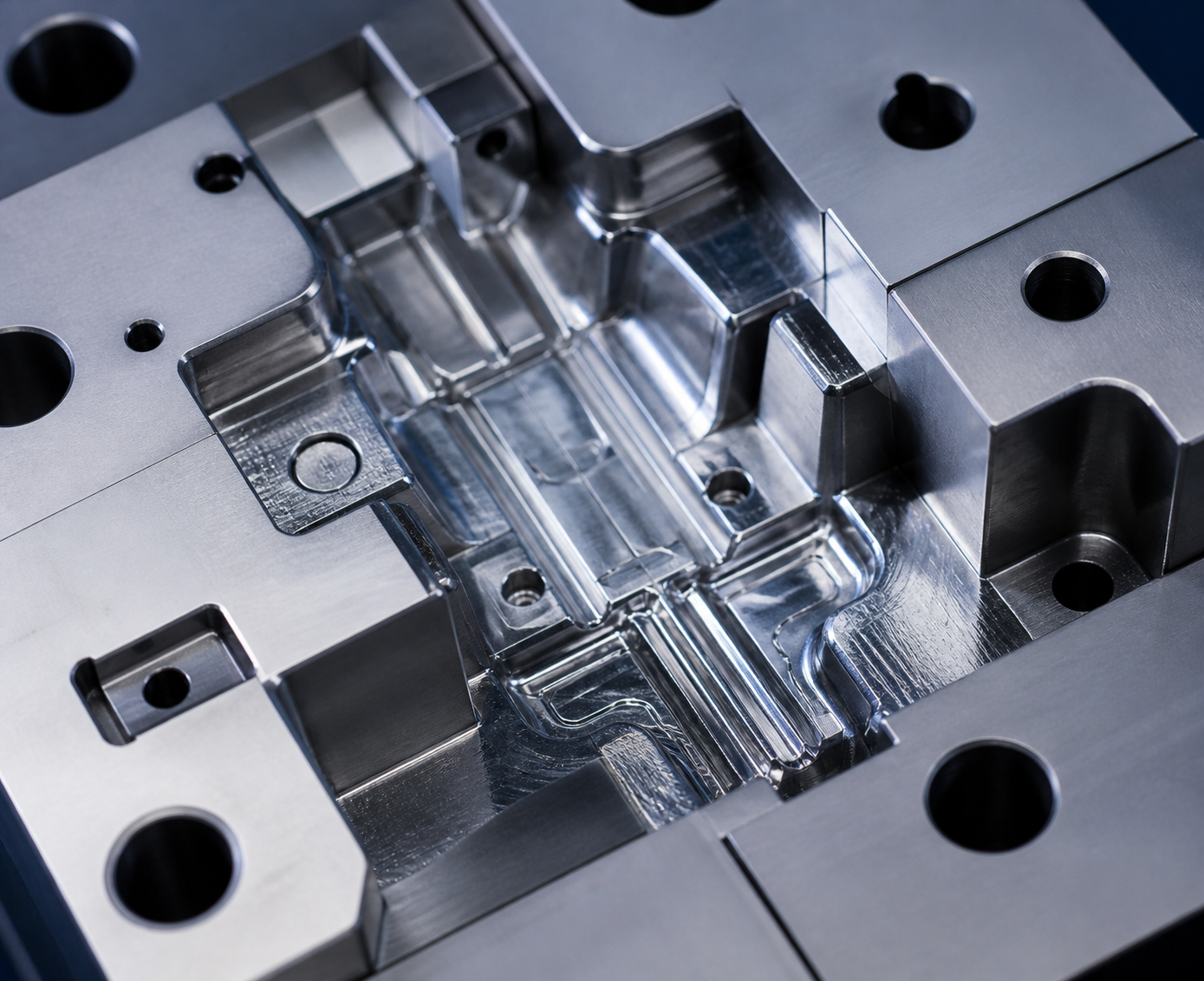
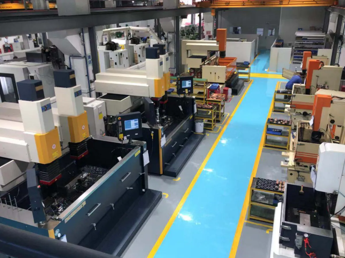
A closer machining view helps connect released tooling information with the physical components being produced.
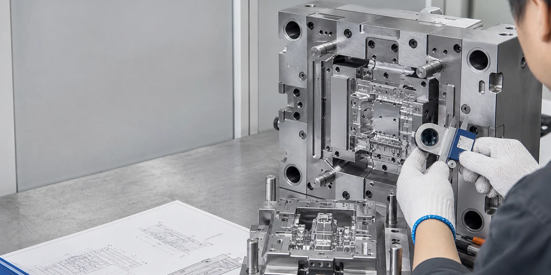
A close physical review supports discussion of component fit, interfaces and mold condition.
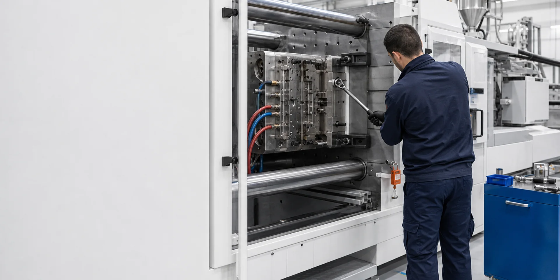
Mold setup provides the manufacturing context for trial activity and the sample review that follows.
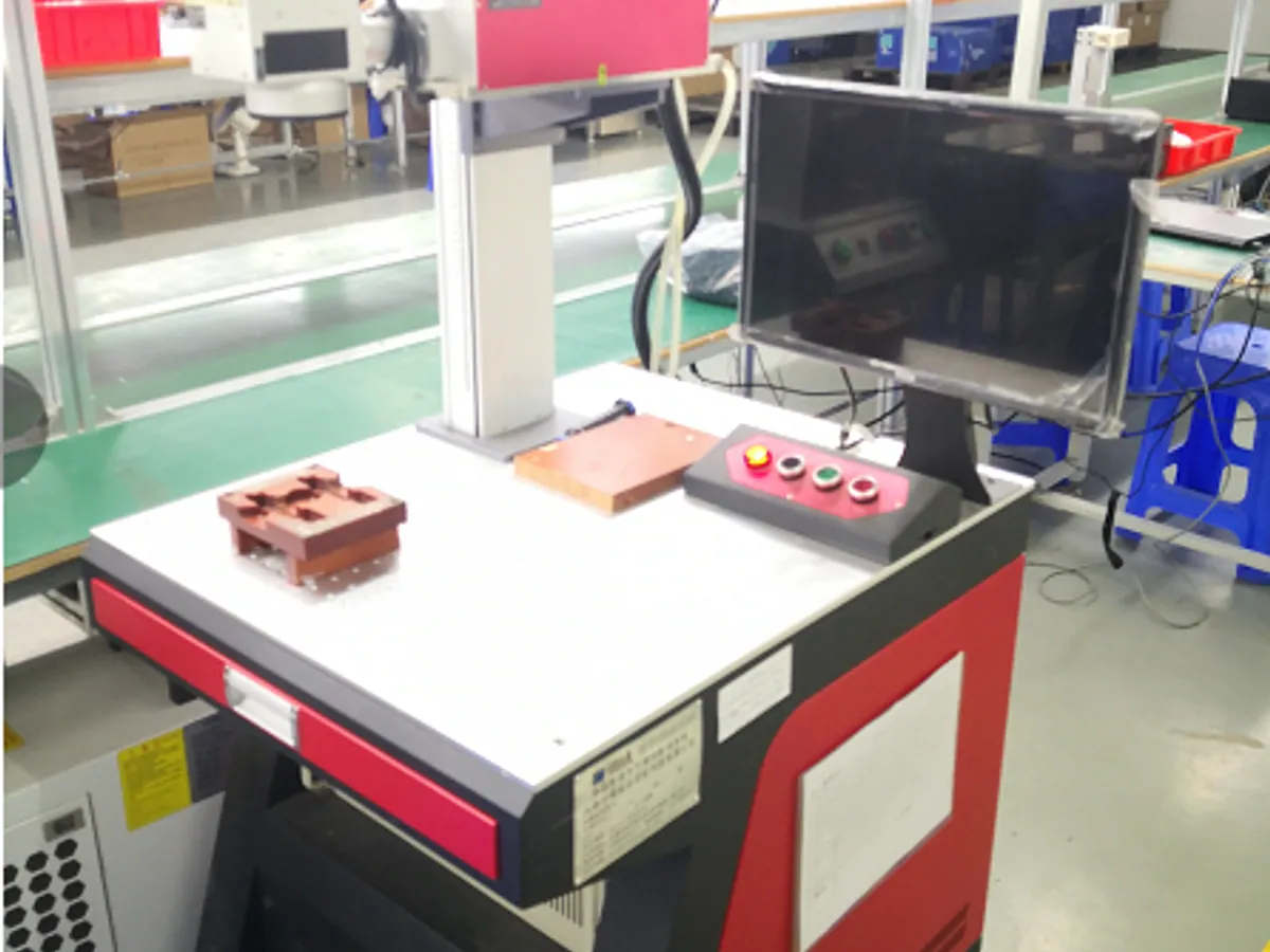
Part, measurement action and reference information keep verification tied to the feature being reviewed.
CONTROL & QUALITY
Compare the tool condition and trial samples with the agreed part drawing and acceptance criteria.
Does the tooling condition reflect the defined part geometry?
Are important part relationships represented in the tooling condition?
Is the physical mold condition ready for the relevant review or trial?
What does the molded sample reveal about tooling or part condition?
Are changes tied to the current approved definition?
START A TOOLING REVIEW
Send your 2D/3D data, resin, mold requirements and target dates. We can then agree feasibility questions, trials and the quotation scope.