Visible housings
Consumer-facing covers connect external form, surface appearance and adjoining-part gaps.


Coffee Machines
Coffee-machine plastic parts, structural components and their molds are a priority for JTO. Scope covers tooling, molding and component operations, not complete appliance manufacture.
INDUSTRY CONTEXT
Across coffee machines, visible covers, control openings, internal supports and removable interfaces must be translated into repeatable molded-part conditions.
Consumer-facing covers connect external form, surface appearance and adjoining-part gaps.
Ribs, bosses and support features organize internal components and assembly loads.
Button, display and service openings require controlled geometry and surrounding surfaces.
Locating, fastening and removable interfaces define how the appliance comes together.
PRODUCT / COMPONENT CONTEXT
Identify the specific coffee-machine component in your drawings, including mating parts, heat or water exposure and any applicable food-contact requirements.
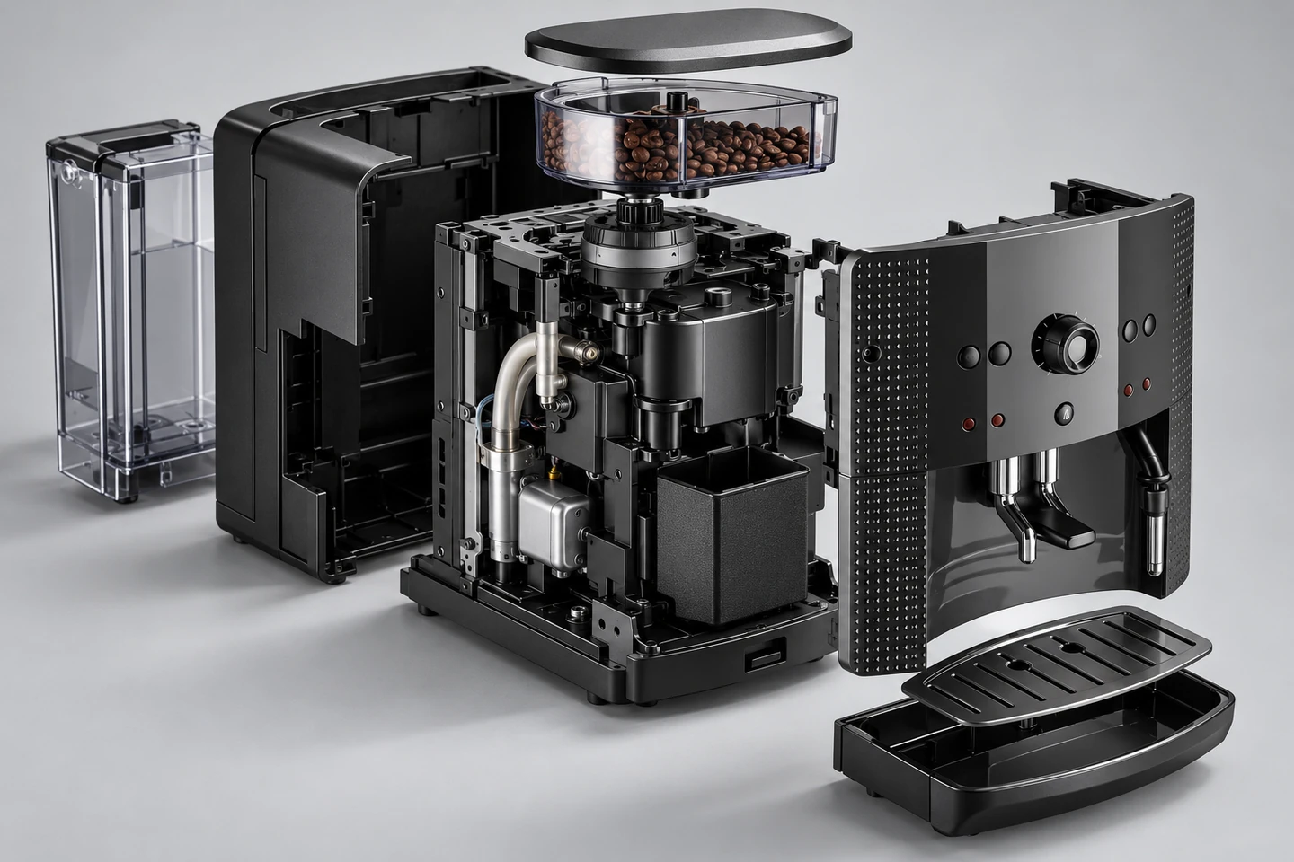
Illustrative coffee-machine components; not a completed appliance or customer project.
Outer shells establish visible form, seams and the boundary around internal structures.
User-touch interfaces combine feel, alignment, attachment and surrounding appearance.
Repeated insertion and removal depend on defined guides, stops and clearances.
Bosses, ribs and brackets connect outer covers to adjoining components.
MANUFACTURING REQUIREMENTS
The manufacturing basis should connect visible surface expectations, structural features, control openings, fit and assembly access across the current revision.
Identify visible zones, texture, color, gloss and handling expectations.
Define seams, gaps, locating features and repeated insertion or removal relationships.
Clarify bosses, clips, screws and support features used to position adjoining parts.
Establish fastening direction, handling space and the sequence constraints around covers.
Keep appearance, fit and attachment references aligned across samples and revisions.
Coffee Machines project information
RELEVANT JTO CAPABILITIES
Relevant capabilities follow the part and assembly requirement, with engineering coordination maintaining the current input and revision basis.
Translate housing form, seams, handle interfaces and attachment features into tooling decisions.
View capabilityConnect material and molding conditions to surface, fit and component consistency.
View capabilityCoordinate finishing, joining and assembly requirements for visible and removable parts.
View capabilityKeep drawings, appearance references and interface decisions aligned through review.
View capabilityCONNECTED MANUFACTURING
A shared definition connects visible finish, mold geometry, molded fit and downstream assembly around the same component relationships.
Identify visible, handled, removable and internally supported component areas.
Align tooling, molding, finishing and assembly requirements around those interfaces.
Compare surface, fit and assembled relationships against the current reference basis.
QUALITY & RISK CONTROL
Quality priorities connect visible surfaces, removable-part fit, assembly relationships and component consistency to the agreed reference.
Compare visible and user-touch areas for texture, color, gloss and handling condition.
Check seams, gaps, guides, stops and locating features around removable parts.
Review fastening, positioning, access and adjoining-part relationships.
Connect dimensional and appearance findings to the current sample and drawing revision.
PROJECT PATH
Start with available part data. Agree the tooling scope, trial samples, checks and approval responsibilities before production.
Part data, product context and open requirements.
Geometry, interfaces, material direction and manufacturing questions.
Tool-related decisions where required by the component path.
Sample condition and comparison basis for the next review.
Relevant dimensional, surface and assembly checks.
Visible findings, actions and readiness decision.
NEXT STEP
Email your drawings, material, quantity and target dates to info@jto.global. Use the Project Guide to prepare any remaining inputs.