Enclosure structure
Wall sections, ribs, bosses and openings establish the component geometry that tooling and molding must resolve.


Outdoor Energy Storage
Specify plastic covers or structural parts, materials and interfaces for energy-storage tooling and molding. Battery and electronic-system assembly are excluded.
INDUSTRY CONTEXT
Structural plastics and enclosure parts bring external form, internal support, joining and service access into the same component review.
Wall sections, ribs, bosses and openings establish the component geometry that tooling and molding must resolve.
Parting interfaces, seals, fasteners and mating edges define how enclosure parts meet.
Mounting points and retained clearances connect the plastic structure to adjoining hardware.
Fastening direction, handling space and removal paths influence downstream assembly decisions.
PRODUCT / COMPONENT CONTEXT
Ribs, bosses, inserts, mating edges and internal supports turn an enclosure concept into a set of connected component decisions.
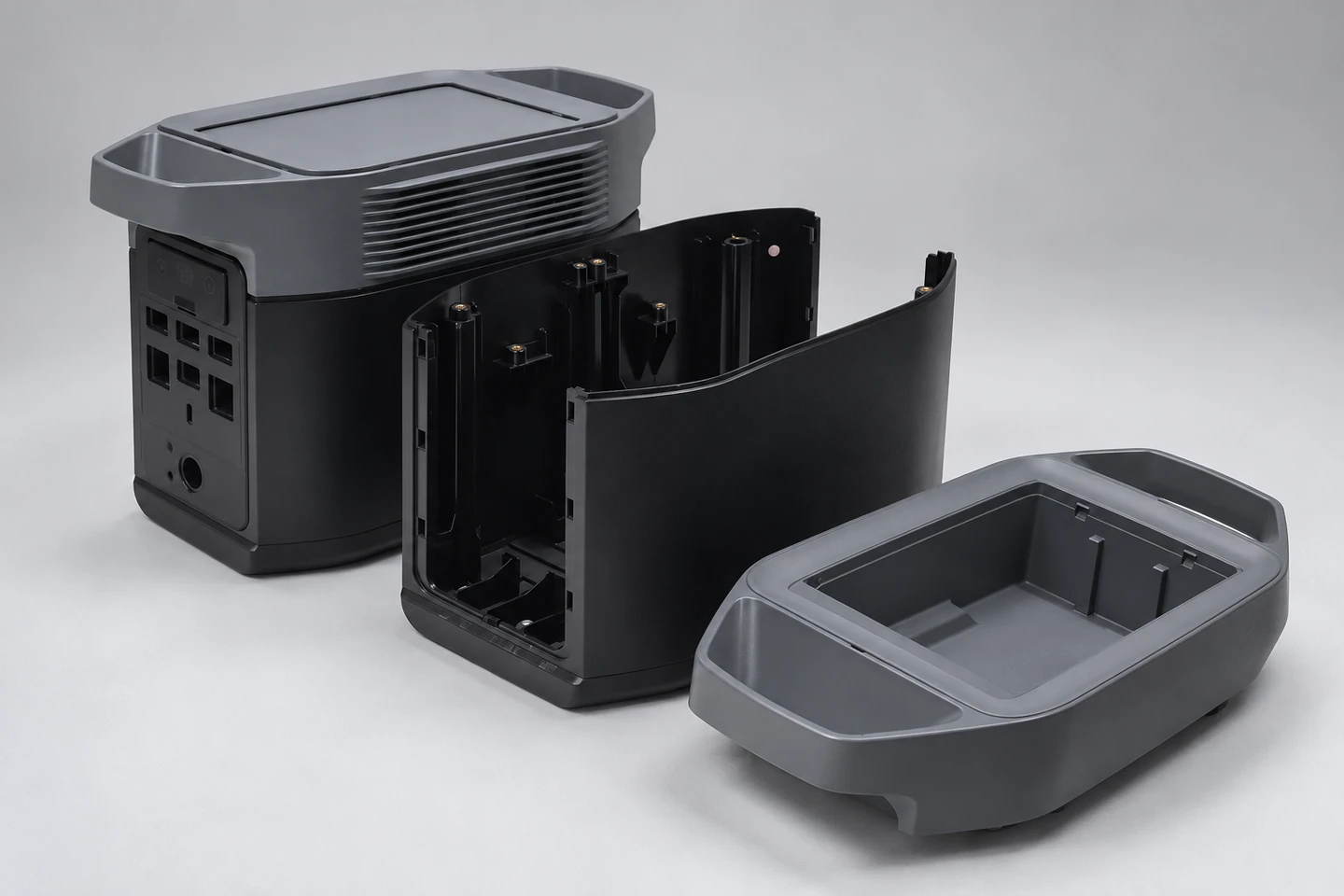
Structural-plastic context showing ribs, bosses, inserts, mounting points and joining edges.
External panels establish overall form, handling surfaces and major joining boundaries.
Reinforcement and fastening features connect stiffness, molding and assembly needs.
Edges, grooves and locating features establish alignment between enclosure parts.
Insert positions and support geometry connect the enclosure to adjoining components.
MANUFACTURING REQUIREMENTS
The review basis should connect component geometry, material direction, joining and revision decisions without extending into battery-system design.
Identify interface dimensions, mounting references and enclosure boundaries for repeatable comparison.
Clarify the material direction and visible or handled surface expectations for each part.
Define how covers, frames, fasteners and adjoining components locate and meet.
Establish fastening, insertion, access and handling requirements for downstream work.
Keep drawing, interface and component changes aligned across tooling, sampling and inspection.
Energy Storage project information
RELEVANT JTO CAPABILITIES
Each capability addresses a different part of the component definition, build and review path.
Translate enclosure geometry, ribs, bosses and mating boundaries into tooling decisions.
View capabilityConnect material direction and molding conditions to dimensional and surface consistency.
View capabilityCoordinate inserts, fastening, joining and downstream handling around the component requirement.
View capabilityMaintain input, revision and review alignment across the enclosure workstream.
View capabilityCONNECTED MANUFACTURING
A shared component basis lets tooling, molding, assembly preparation and review points address the same interfaces and revisions.
Clarify enclosure geometry, material direction, joining edges and mounting relationships.
Align tooling, molding and downstream operations around the component interfaces.
Compare samples and inspection findings against the current drawing and assembly basis.
QUALITY & RISK CONTROL
Quality review connects dimensions, material and surface condition, mating interfaces and assembled condition to the applicable revision.
Check interface dimensions, locating points and critical enclosure boundaries.
Compare material identification and surface condition with the agreed basis.
Review cover fit, joining edges, mounting points and fastening relationships.
Confirm positioning, access and finished enclosure relationships at the defined review stage.
PROJECT PATH
Start with available part data. Agree the tooling scope, trial samples, checks and approval responsibilities before production.
Part data, product context and open requirements.
Geometry, interfaces, material direction and manufacturing questions.
Tool-related decisions where required by the component path.
Sample condition and comparison basis for the next review.
Relevant dimensional, surface and assembly checks.
Visible findings, actions and readiness decision.
NEXT STEP
Email your drawings, material, quantity and target dates to info@jto.global. Use the Project Guide to prepare any remaining inputs.