
PART REQUIREMENTPrecision Tooling

CAPABILITIES
Tooling and molding, linked by engineering.
JTO provides mold design and build, injection molding, component finishing and assembly, supported by engineering coordination.
CAPABILITY
Precision Tooling
From DFM and mold design through machining, fitting, trial and modification.
Part geometry, material direction, appearance and functional requirements are carried into a practical mold design and build path.
- DFM and tooling input review
- Mold concept, gate and parting direction
- Machining, fitting and build checkpoints
- Trial results, modification and verification
Released 2D/3D data establishes the working baseline. Machining and fitting follow the reviewed mold direction, while trial findings guide the modifications needed before the next verification step.
Precision Tooling project data
- Mold design
- Injection molds; agree construction and trial requirements from the part data
- Size inputs
- Provide the mold envelope, weight and target press for feasibility assessment
- Tooling inputs
- Current 2D/3D data, material, surface and quality requirements
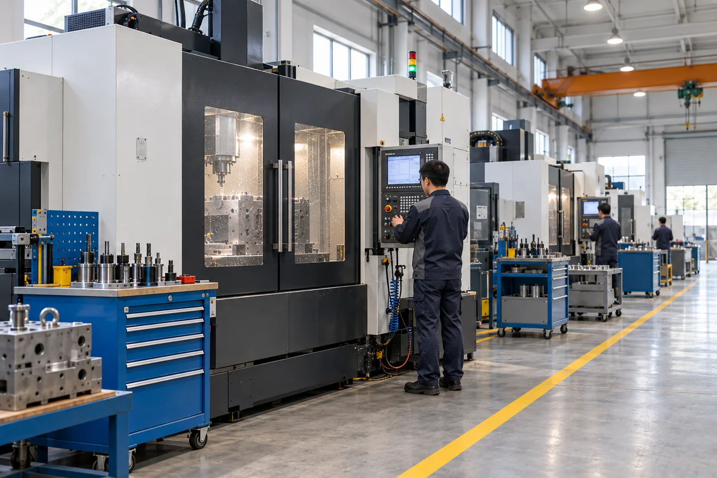
Machining and tooling-build environment.
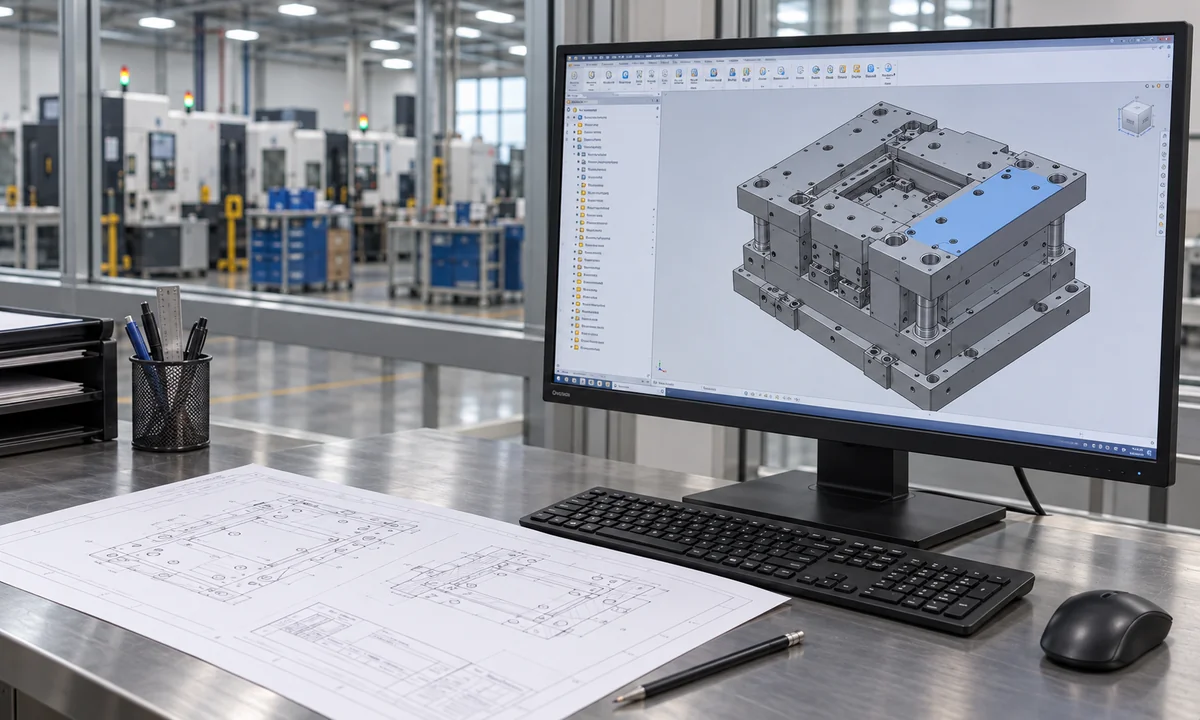
CAD and physical tooling reviewed together.
CAPABILITY
Injection Molding
Coordinate material, tool, machine, sampling and production conditions around the part.
Part requirements and tool readiness are brought into a controlled setup for sampling, process review and production.
- Part, tool and molding-input review
- Material direction and machine matching
- Sampling and first-piece review
- Process and production checkpoints
Part data, tool condition and material direction are reviewed before machine setup. Sampling and first-piece findings then establish the checkpoints carried into the applicable production process.
Injection Molding project data
- Material experience
- ABS · PC · PP · PA · PMMA · PC/ABS · POM · TPU · TPE
- Process scope
- Injection molding and two-shot molding; confirm other production routes separately
- Part requirements
- Geometry, material, expected volume, appearance and inspection basis
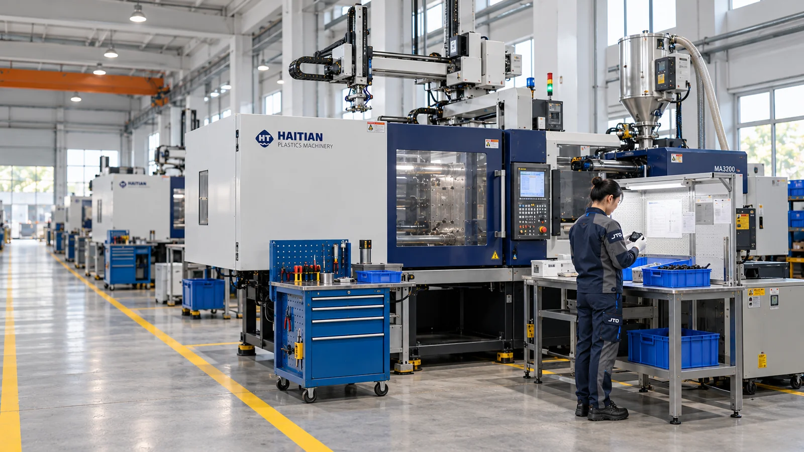
Injection molding machines with an adjacent handling station.
CAPABILITY
Secondary Process & Assembly
Organize trimming, surface processes, joining and assembly around the required finished state.
The required finished state defines the operation, fixture, interface checks and handling needed after molding.
- Trimming and selected surface processes
- Joining methods and fixture-based work
- Part, hardware and interface assembly
- Finished-state checks, protection and handling
The finished condition is defined first, then the required operations and work references are organized around mating surfaces, cosmetic areas, assembly interfaces and the final handling handoff.
Secondary Process & Assembly project data
- In-house processes
- Painting · screen/pad printing · laser processing · heat and ultrasonic joining
- Partner process
- UV treatment is externally supported; confirm scope by project
- Assembly boundary
- Component assembly only; no complete-product, electronic-system or battery assembly
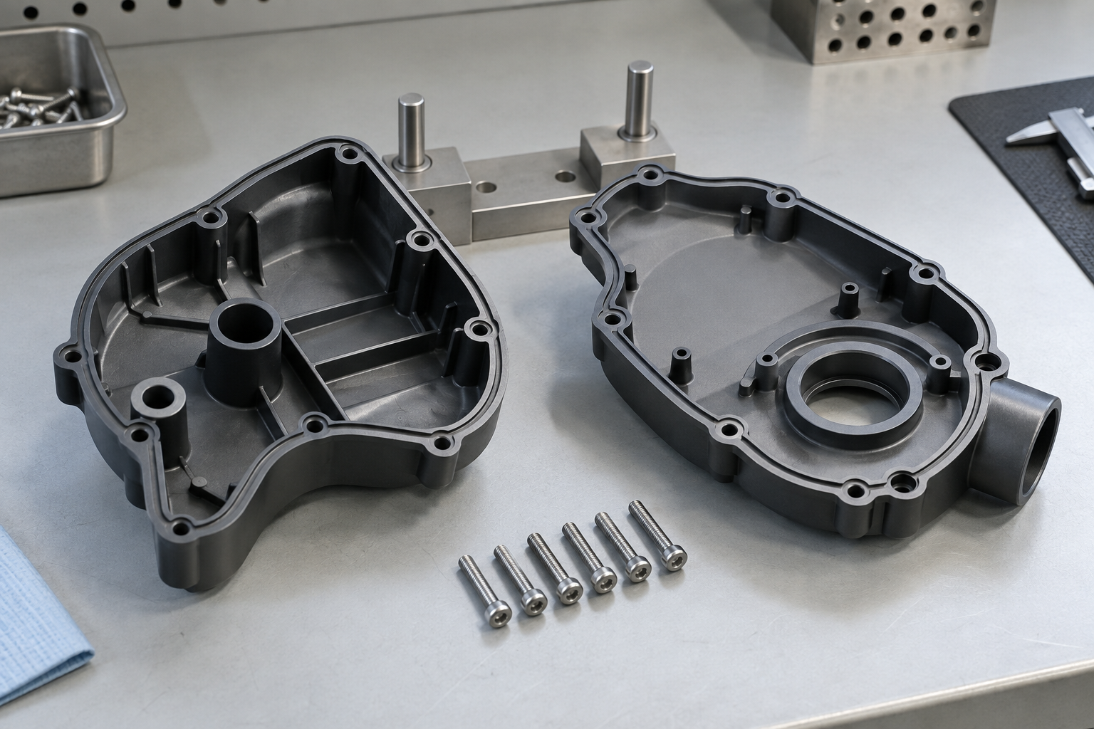
Illustrative component interfaces and fasteners; material and project identity are not established by this image.
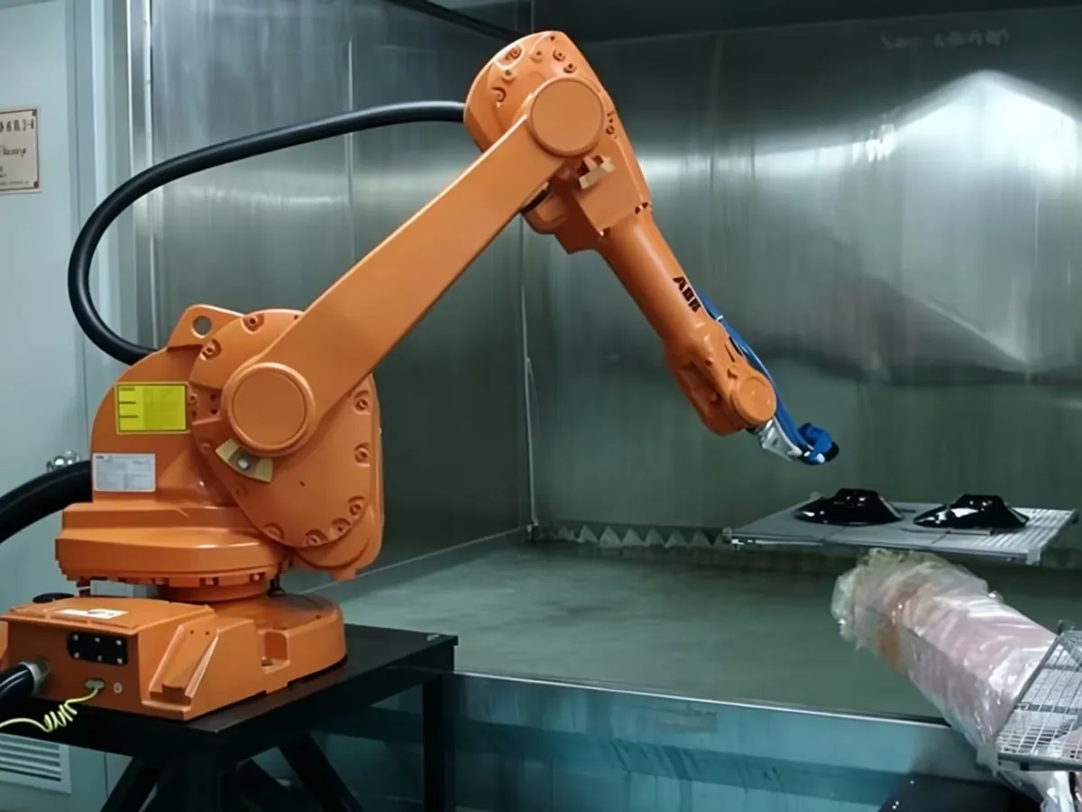
Controlled secondary operation on molded parts.
CAPABILITY
Engineering & Project Management
Keep drawings, revisions, owners, milestones and records connected across the work.
Cross-stage engineering support connects input review, change control, milestone coordination and progress records.
- Drawing and requirement baseline
- Revision, issue and change control
- Review ownership and milestone coordination
- Decision, progress and follow-up records
A shared working baseline keeps released data, open issues and review ownership visible across tooling, molding and assembly checkpoints, with changes and milestone decisions recorded for follow-up.
Engineering & Project Management project data
- Review baseline
- Current drawing/CAD revision and part requirements
- Coordination
- DFM, tooling, sampling, change and milestone review
- Open decisions
- Owners, affected interfaces and next verification step
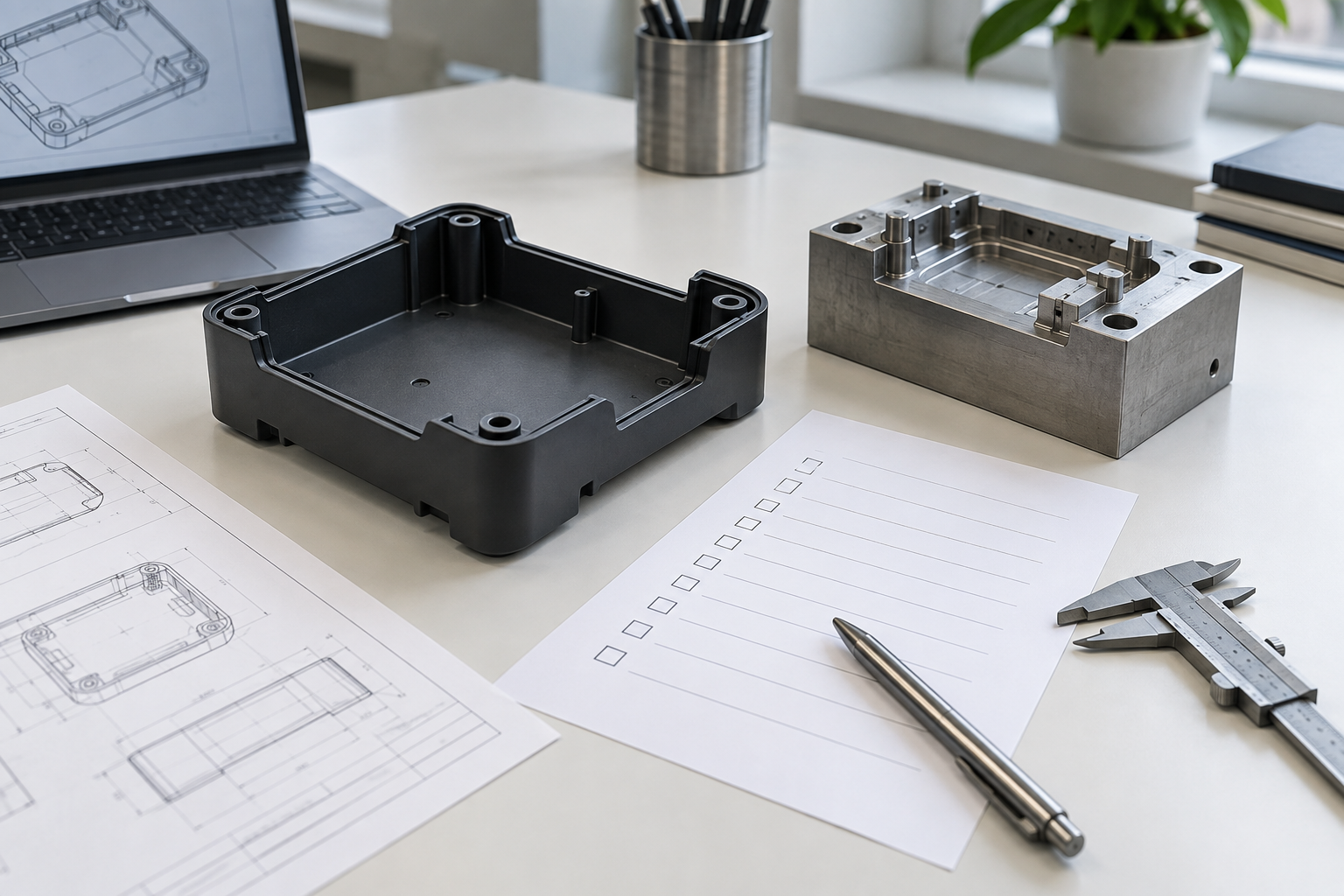
Illustrative part, tooling and engineering-input context.
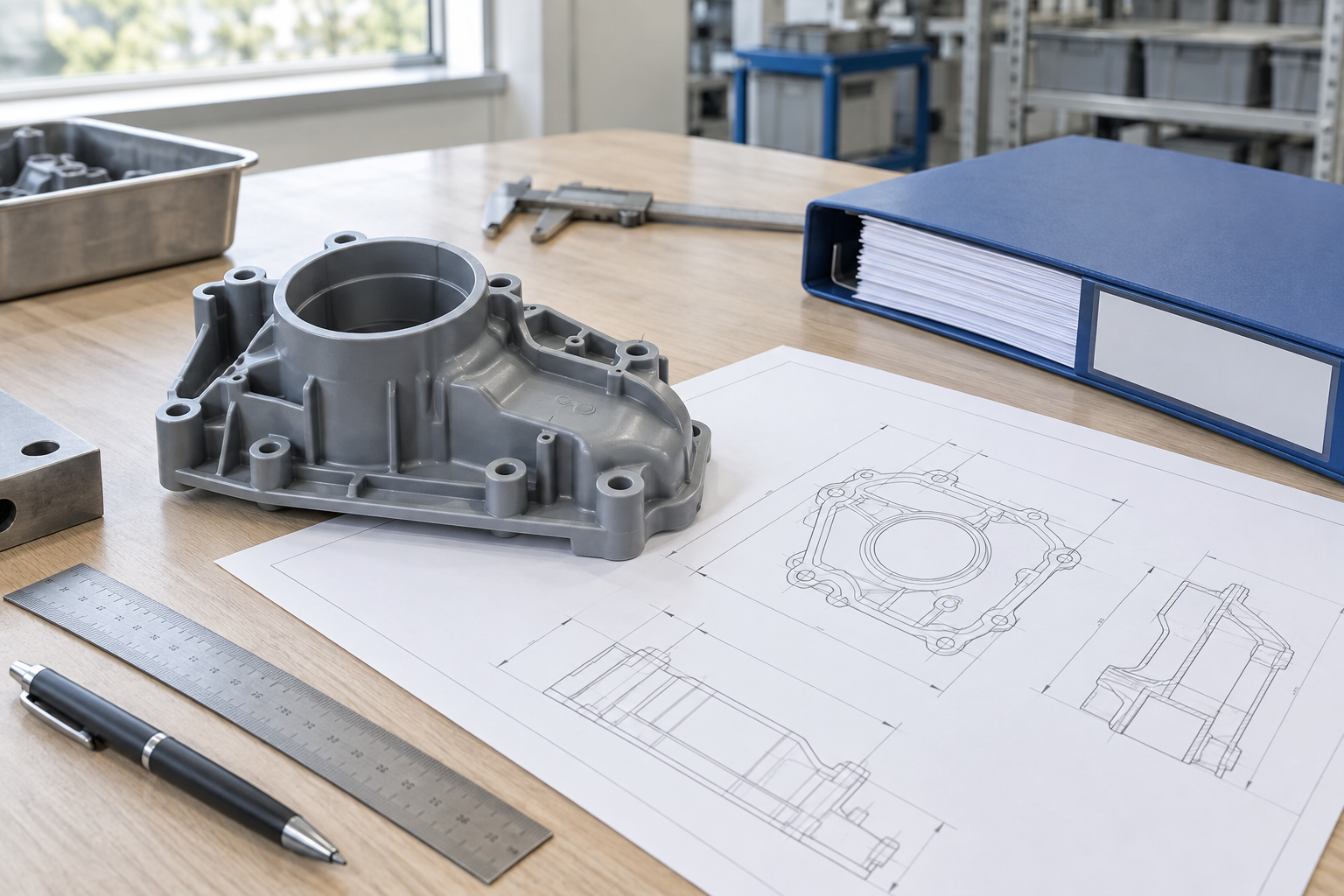
Illustrative component and documents on a review desk.
HOW CAPABILITIES CONNECT
Manufacturing feedback moves both ways.
A project may enter through tooling, molding, or downstream operations. Trial results, part findings and assembly requirements can move upstream, while engineering coordination spans the work that applies.
ENGINEERING & PROJECT MANAGEMENT
Drawing · Revision · Ownership · Milestones · Records · Progress
TOOL / MATERIALInjection Molding
FINISHED STATESecondary Process & Assembly
ENGINEERING / PROJECT CONTROL CONTINUITY
Drawing review
Requirements stay tied to the released working data.
Build checkpoint
Reviewed findings are recorded before work moves forward.
Change control
Revisions, owners and affected interfaces remain connected.
Progress record
Milestone decisions and follow-up items remain visible.
DISCUSS YOUR PROJECT
Share the project inputs that are ready.
Send your drawings, resin requirements, quantity, inspection criteria and target dates to discuss scope and next steps.